In the contouring mode, you can program an arbitrary path via a series of points. Between the points, linear interpolation is performed, leading to a contour described by a succession of linear segments. The contouring mode may be executed only from a TML program. You can’t send contouring points from a host via a communication channel, like in the case of the PT mode. Depending on the control mode chosen, four options are available:
| • | Position contouring – the load/motor is controlled in position. The path represents a position reference |
| • | Speed contouring – the load/motor is controlled in speed. The path represents a speed reference. |
| • | Torque contouring – the motor is controlled in torque. The path represents a current reference. |
| • | Voltage contouring – the motor is controlled in voltage. The path represents a voltage reference. |
A contouring segment is described via the TML command SEG, which has 2 parameters: time and reference increment. The time represents the segment duration expressed in time units i.e. in number of slow loop sampling periods. The reference increment represents the amount of reference variation per time unit i.e. per slow loop sampling period.
The contouring mode has been foreseen mainly for setup tests. However, you can also use the position contouring and the speed contouring for normal operation, as part of your motion application. You can switch at any moment to and from these 2 modes. The torque contouring and the voltage contouring have been foreseen only for setup tests. The torque contouring may be used, for example, to check the response of the current controllers to different input signals. Similarly, the voltage contouring may be used, for example, to check the motors behavior under a constant voltage or any other voltage shape.
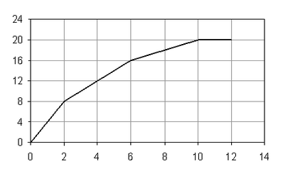
Reference generation in contouring modes
In position contouring or speed contouring, the starting point is either the current value of the target position/speed (if TUM1 command is set between the motion mode setting and the UPD command), or the actual value of the load position/speed (if TUM1 is omitted). Therefore the contour is relative to the starting point.
In torque/voltage contouring, the starting point may be set by the user in REF0(H). After reset, the default value of REF0(H) is zero.
In the TML program, first the contouring mode must be set, followed by the first point. Then the contouring mode can be activated with the UPD command, followed by the next points. The sequence of points must end with a final point having the time interval 0.
Remarks:
| • | When the last segment execution ends, the reference is kept constant at the last computed value. |
| • | When a contouring sequence ends without having time value set to 0 on the last segment, the drive/motor remains in contouring mode waiting for new points. When the last segment has time value set to 0, the drive gets out from contouring mode. In order to execute other segments, the contouring mode must be set again. |
When a sequence of contour points is executed, the TML instruction pointer IP advances as the segments described by the points are executed. When the reference generator starts working with a new segment, at TML program level the IP advances to the execution of the SEG instruction. The execution of a TML instruction for a contour segment means to copy the segment data into a local buffer and then wait (i.e. loop on the same instruction) until the previous segment, currently under execution at reference generator level will end. This procedure permits to immediately start the execution of the next contour segment when the current one ends because the next segment data are already available in a local buffer. Each time the reference generator starts to execute a new segment, the IP advances to the next contour segment and its data are transferred into the local buffer.
See also: