MCR is a 16-bit status register containing information about the motion modes, reference mode, active control loops, positioning type - absolute or relative, etc.
TML Address: 0x0309
Contents. MCR information is structured as follows:
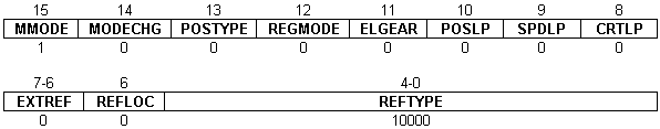
Bit 15 MMODE. Motion mode
0 = |
Same motion mode |
1 = |
New motion mode |
Bit 14 MODECHG. When motion mode is changed
0 = |
Update the reference |
1 = |
Keep the reference |
Bit 13 POSTYPE. Positioning type
0 = |
Relative |
1 = |
Absolute |
Bit 12 REGMODE. Motion superposition
0 = |
Disable the superposition of the electronic gearing mode with a second motion mode |
1 = |
Enable the superposition of the electronic gearing mode with a second motion mode |
Bit 11 ELGEAR. Electronic gearing master
0 = |
Disable the axis as master |
1 = |
Enable the axis as master |
Bit 10 POSLP. Position loop status
0 = |
Disabled |
1 = |
Enabled |
Bit 9 SPDLP. Speed loop status
0 = |
Disabled |
1 = |
Enabled |
Bit 8 CRTLP. Current loop status
0 = |
Disabled |
1 = |
Enabled |
Bit 7-6 EXTREF. External reference type
00 = |
On-line reference |
01 = |
Analogue reference |
10 = |
Digital reference |
11 = |
Reserved |
Bit 5 REFLOC. Analogue external reference for torque/voltage mode update
0 = |
Update in slow control loop |
1 = |
Update in fast control loop |
Bit 4-0 REFTYPE. Reference type
00000 = |
External reference |
00001 = |
Trapezoidal reference |
00010 = |
Contouring position/speed |
00011 = |
Contouring torque/voltage |
00100 = |
Pulse & direction |
00101 = |
Electronic gearing slave |
00110 = |
Electronic camming slave |
00111 = |
S-curve reference |
01000 = |
Test mode |
01001 = |
PVT |
01010 = |
PT |
10000 = |
Stop 0/1/2 |
10001 = |
Stop using trapezoidal profile |
10100 = |
Stop using S-curve profile |
10101 = |
Quickstop |