OSR is a 16-bit configuration register, defines some specific operating settings regarding motor control and data acquisition
TML Address: 0x0302
Contents. OSR information is structured as follows:
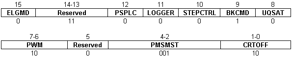
Bit 15 ELGMD. Electronic gearing master mode
0 = |
Send actual position to slave axes |
1 = |
Send target position to slave axes |
Bit 14-13 Reserved
Bit 12 PSPLC. Position sensor mounting place
0 = |
Position sensor on motor |
1 = |
Position sensor on load |
Bit 11 LOGGER. PMSM start logging
0 = |
No data logging during PMSM motor start |
1 = |
Data logging during PMSM motor start |
Bit 10 STEPCTRL. Stepper motor control type
0 = |
Open loop |
1 = |
Closed loop |
Bit 9 BKCMD. Brake command
0 = |
Disabled |
1 = |
Enabled |
Bit 8 UDQSAT. Ud,q command saturation method
0 = |
Use independently saturated commands on d and q axes |
1 = |
Compute Uq from Ud. Uq = f(Ud) |
Bit 7-6 PWM. PWM command method
00 = |
Standard symmetric PWM |
01 = |
Dead-time and Vdc compensation |
10 = |
Dead-time, Vdc compensation and third harmonic injection |
11 = |
Reserved |
Bit 5 Reserved
Bit 4-2 PMSMST. PMSM motor start method
000 = |
Reserved |
001 = |
a/b, voltage mode, incremental encoder |
010 = |
Start using digital Hall sensors |
011 = |
Reserved |
100 = |
Reserved |
101 = |
Motionless start (encoder only) * |
110 = |
Reserved |
111 = |
Direct start using absolute encoder |
Bit 1-0 CRTOFF. Current offset detection
00 = |
No current offset detection |
01 = |
Detection without PWM activated |
10 = |
Detection with PWM activated |
11 = |
Reserved |
*On select firmware versions only