The main section of a TML program starts with the instruction BEGIN and ends with the instruction END. It is divided into two parts:
| • | Setup part |
| • | Motion programming part |
The setup part starts after BEGIN and lasts until the ENDINIT instruction, meaning “END of INITitialization”. This part of the TML program consists mainly of assignment instructions, which shall set the TML registers and the TML parameters in accordance with your application data. When the ENDINIT command is executed, key features of the TML environment are initialized according with the setup data. After the ENDINIT execution, the basic configuration involving the motor and sensors types or the sampling rates cannot be changed unless a reset is performed.
Remark: The setup part can be void when setup data is saved in the EEPROM. In this case, the setup data is automatically loaded into the TML registers and parameters, at power-on. However, even in this case in some situations it may still be necessary to perform some setup operations like:
| • | Copy of cam tables from the drive/motor EEPROM into the working RAM memory |
| • | Copy of the whole TML program into the RAM in special cases where the EEPROM memory can’t be used during run time |
The motion programming part starts after the ENDINIT instruction until the END instruction. All the TML programs (the main section) should end with the TML instruction END. When END instruction is encountered, the sequential execution of a TML program is stopped.
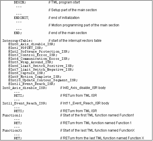
Apart from the main section, a TML program also includes the TML interrupt vectors table, the interrupt service routines (ISRs) for the TML interrupts and the TML functions. A typical structure for a TML program is presented in figure below.
Typical structure of a TML Program
Basic Concepts next topics:
Memory Map – Firmware version FAxx
Memory Map – Firmware version FBxx
See also: