Most of the Technosoft drives/motors can communicate via CAN-bus. The CAN-bus communication is multi-point, half duplex, and enables you to link up to 32 drives/motors in a network.
The major advantage of the CAN-bus is its capability to solve automatically the conflicts. On a CAN-bus network, if two devices start to transmit in the same time, one of them (having the higher priority) always wins the network access and completes the transmission. The other device, after losing the network access, commutes from transmission to reception, receives the message with the higher priority, then tries again to transmit its own message. All this procedure is done automatically by the hardware (CAN-bus controller) and it is transparent at higher levels. Put in other words, one can work with a CAN-bus network like being full duplex, knowing that if transmission conflicts occur, these are automatically solved.
Technosoft drives/motors have been specifically designed to exploit the CAN-bus benefits. For example, in multi-axis applications you can really distribute the intelligence between the master and the drives/motors. Instead of trying to command each step of an axis movement, you can program the drives/motors using TML to execute complex tasks and inform the master when these are done. Thus for each axis the master task may be reduced at: calling TML functions (with possibility to abort their execution if needed) and waiting for a message, which confirms the execution. If needed, the drives/motors may also be programmed to send periodically information messages to the master so it can monitor a task progress.
Depending on product, Technosoft drives/motors are delivered either with TMLCAN protocol or with CANopen. On request, the TMLCAN protocol, which is based on CAN2.0B, may be replaced with TechnoCAN protocol which is based on CAN2.0A. TechnoCAN was specifically designed to permit connection of the Technosoft drives/motors without CANopen on a CANopen network where messages are exchanged using CANopen protocol. TechnoCAN and CANopen do not disturb each other and therefore can co-exist on the same physical bus.
Message encapsulation in TMLCAN protocol
TMLCAN is based on CAN2.0B using 29 bits for the identifier. It accepts the following baud rates: 125kb, 250kb, 500kb (default after reset), 800kb and 1Mb.
The message destination (an axis or a group of axes) and the TML instruction binary code are encapsulated as follows:
CAN message identifier of a message sent to:
Axis
![]()
Group
![]()
Broadcast
![]()
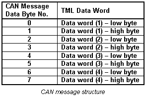
CAN message data bytes:
Message types on CAN-bus communication
The CAN-bus communication is based on 3 types of messages imposed by the nature of the TML commands encapsulated:
| • | Type A: Messages that don’t require an answer (a return message). These messages can be sent either by a host or by another drive/motor and contain TML instructions performing parameter settings, motion programming, motor commands, etc. |
| • | Type B: Messages that require an answer. These messages are sent by a host and contain one of the on line TML commands. These commands ask to return data, for example the value of a TML parameter, register, or variable. |
| • | Type C: Messages sent by a drive/motor to a host without being requested by the host. These messages may be sent either when a specific condition occurs or following the execution of the TML command SEND (see Messages sent to the host for details) |
The next paragraphs present an example of each message type.
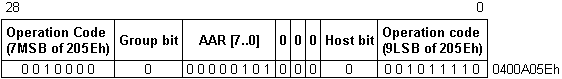
Example 1 – Type A Message: A host connected on CAN-bus sends to drive/motor with axis ID = 5 the TML instruction “KPP = 0x1234” (set proportional part of the position controller with value 0x1234). The TML instruction binary code are:
Binary code of TML instruction KPP =0x1234
![]()
Remark: Use Binary Code Viewer to get the binary code of TML instructions
The CAN message identifier is:
CAN message identifier: TML instruction KPP =0x1234 sent to axis 5
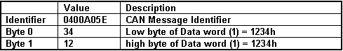
The host must send a CAN message with the following contents:
CAN message: TML instruction KPP =0x1234 sent to axis 5
Example 2 – Type B Message: A host wants to get the position error of 2 drives/motors, which are members of group 1. The host axis ID is 3 and the drives/motors axis ID are 5 and 7. The position error is the 16-bit TML variable named POSERR and its address in the TML data memory is 0x022A. The host sends to group 1 a “GiveMeData2” request for the TML variable POSERR and waits for the “TakeData2” answers.
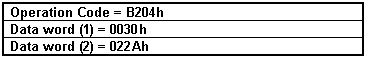
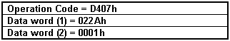
The Group ID Code and the binary code of “GiveMeData2” request for POSERR are:
Binary code of GiveMeData2 request for POSERR value sent to group 1
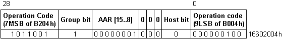
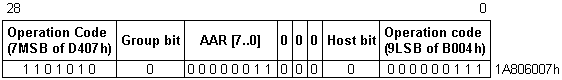
The CAN message identifier is:
CAN message identifier: GiveMeData2 request for POSERR value sent to group 1
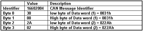
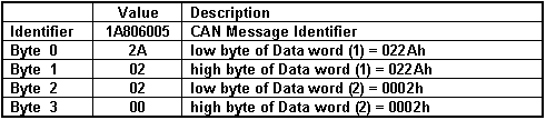
The host must send a CAN message with the following contents:
CAN message: GiveMeData2 request for POSERR value sent to group 1
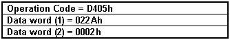
Supposing that the drive/motor with Axis ID = 5 returns a position error POSERR = 2, the binary code of the “TakeData2” answer is:
Binary code of TakeData2 with POSERR value from axis 5
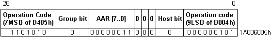
The CAN message identifier is:
CAN message identifier: TakeData2 with POSERR value from axis 5
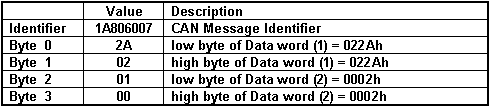
The host gets a CAN message with the following contents:
CAN message: TakeData2 with POSERR value from axis 5
Supposing that the drive/motor with Axis ID = 7 returns a position error POSERR = 1, the binary code of the “TakeData2” answer is:
Binary code of TakeData2 with POSERR value from axis 7
The CAN message identifier is:
CAN message identifier: TakeData2 with POSERR value from axis 7
The host gets a CAN message with the following contents:
CAN message: TakeData2 with POSERR value from axis 7
Example 3 – Type C Message: A host is connected to a drive via CAN-bus and wants to be informed when the programmed motion is completed. The host axis ID = 255 and the drive/motor axis ID = 1. A Type C message is a “TakeData2” message sent without a “GiveMeData2” request. It includes the following information:
“TakeData2” – Message description
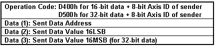
The destination axis is provided by the TML variable MASTERID, according with formula: MASTERID = host axis ID * 16 + 1. In this example, the 8-bit host axis ID = 255, hence MASTERID = 16 * 255 + 1 = 4081 (0xFF1). In the case of a Type C message, the “TakeData2” can return:
| • | The 32-bit value of the 2 status registers SRL (bits 15-0) and SRH (bits 31-16), if one of their selected bits changes (the requested data address is the SRL address) |
| • | The 16-bit value of the error register MER, if one of its selected bits changes |
| • | The 16-bit value of the PVT/PT status PVTSTS, if PVT/PT buffer status changes |
| • | The 16-bit or 32-bit TML data requested to be sent with the TML command SEND. |
Remark: Use Command Interpreter to get the addresses for the above TML data. Note that the SRL and SRH status registers may also be accessed as a single 32-bit variable named SR32.
The bit selection is done via 3 masks, one for each register, set in TML parameters: SRL_MASK, SRH_MASK, MER_MASK. A bit set in a mask, enables a message transmission when the same bit from the corresponding register changes. In this example, the motion complete condition is signaled by setting SRL.10 = 1. To activate automatic sending of a “TakeData2” whenever SRL.10 changes, set SRL_MASK = 0x0400.
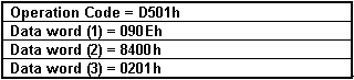
Supposing that the drive/motor with Axis ID = 1 returns SRH = 0x201 and SRL = 0x8400, after SRL.10 goes from 0 to 1, the Axis ID Code and the binary code of the “TakeData2” message is:
Axis ID Code + Binary code of TakeData2 with status registers SRL and SRH from axis 1
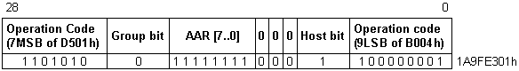
The CAN message identifier is:
CAN message identifier: TakeData2 with status registers SRL and SRH from axis 1
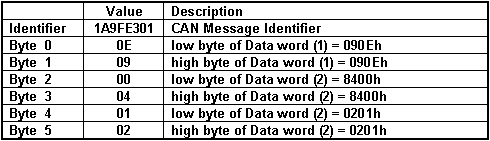
The host gets a CAN message with the following contents:
CAN message: TakeData2 with status registers SRL and SRH from axis 1
Remark: A “TakeData2” message with SRL.10=1 signals that the last programmed motion is completed. A “TakeData2” message with SRL.10=0 signals that a new motion has started and may be used as a confirmation for the last motion command.
See also:
Communication protocols – Overview
CAN-bus communication. TechnoCAN protocol
